
【嵌入式Linux】15-裸机-NXP官方SDK使用
此笔记由个人整理塞上苍鹰_fly课程来自:正点原子_手把手教你学Linux一、官方SDK移植1、新建cc.h文件SDK包里面会使用到很多数据类型,所以我们需要在cc.h里面定义一些常用的数据类型2、移植文件设备为MCIMX6Y2MCIMX6Y2.hfsl_common.hfsl_iomuxc.h3、修改移植文件fsl_common.h删除所有包含的头文件,包含进入自己定义的cc.h文件删除**ty
·
此笔记由个人整理
塞上苍鹰_fly
课程来自:正点原子_手把手教你学Linux
一、官方SDK移植
1、新建cc.h文件
- SDK包里面会使用到很多数据类型,所以我们需要在cc.h里面定义一些常用的数据类型
2、移植文件
-
设备为MCIMX6Y2
-
MCIMX6Y2.h
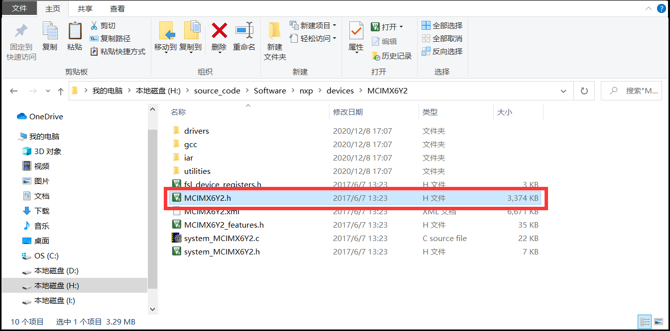
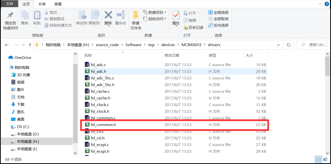
- fsl_common.h
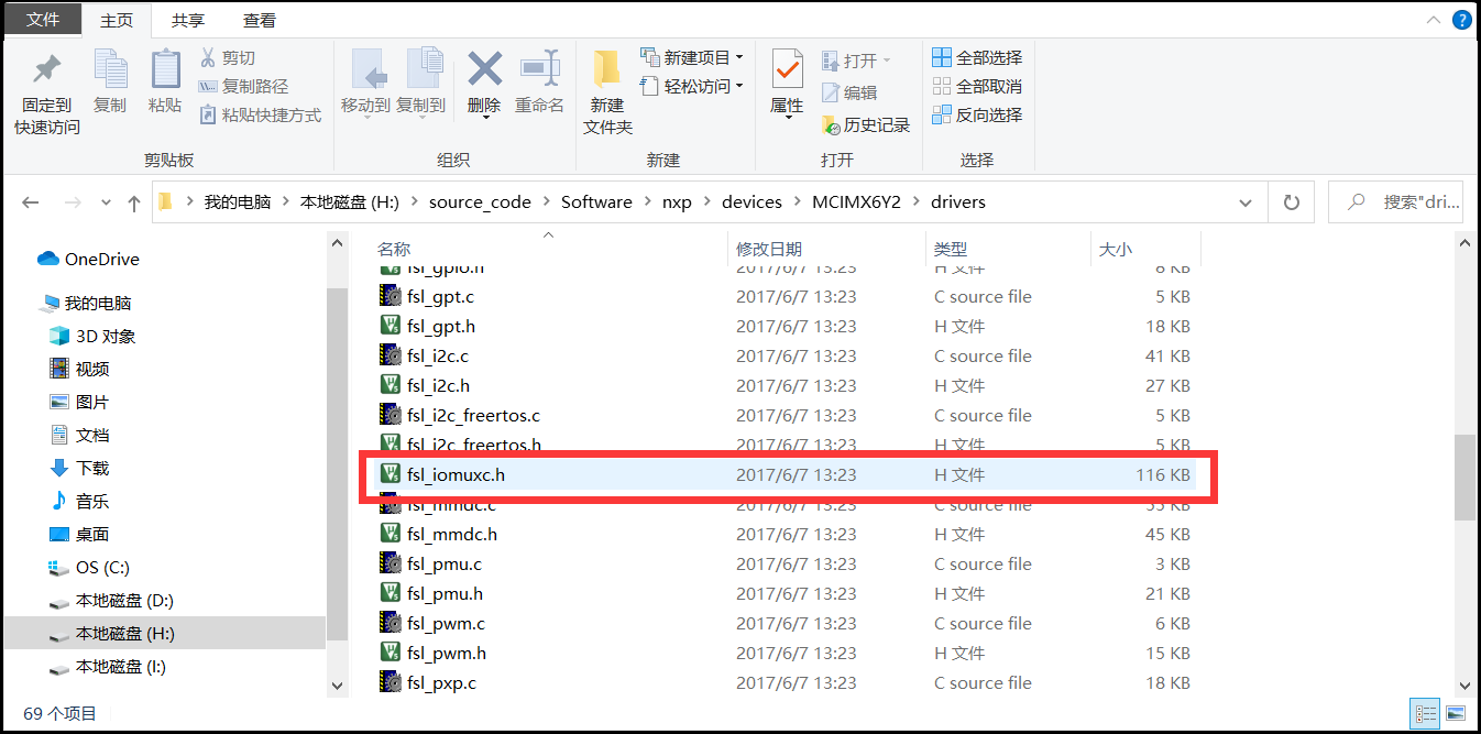
- fsl_iomuxc.h
3、修改移植文件
- fsl_common.h
- 删除所有包含的头文件,包含进入自己定义的cc.h文件
- 删除**typedef int32_t status_t;**后的所有
- 在最后添加**#endif /* FSL_COMMON_H /*
#ifndef _FSL_COMMON_H_
#define _FSL_COMMON_H_

#include "cc.h"				/* cc.h为自行添加的文件 */
/*!
 * @addtogroup ksdk_common
 * @{
 */

/*******************************************************************************
 * Definitions
 ******************************************************************************/

/*! @brief Construct a status code value from a group and code number. */
#define MAKE_STATUS(group, code) ((((group)*100) + (code)))

/*! @brief Construct the version number for drivers. */
#define MAKE_VERSION(major, minor, bugfix) (((major) << 16) | ((minor) << 8) | (bugfix))

/* Debug console type definition. */
#define DEBUG_CONSOLE_DEVICE_TYPE_NONE 0U     /*!< No debug console.             */
#define DEBUG_CONSOLE_DEVICE_TYPE_UART 1U     /*!< Debug console base on UART.   */
#define DEBUG_CONSOLE_DEVICE_TYPE_LPUART 2U   /*!< Debug console base on LPUART. */
#define DEBUG_CONSOLE_DEVICE_TYPE_LPSCI 3U    /*!< Debug console base on LPSCI.  */
#define DEBUG_CONSOLE_DEVICE_TYPE_USBCDC 4U   /*!< Debug console base on USBCDC. */
#define DEBUG_CONSOLE_DEVICE_TYPE_FLEXCOMM 5U /*!< Debug console base on USBCDC. */
#define DEBUG_CONSOLE_DEVICE_TYPE_IUART 6U    /*!< Debug console base on i.MX UART. */
#define DEBUG_CONSOLE_DEVICE_TYPE_VUSART 7U   /*!< Debug console base on LPC_USART. */

/*! @brief Status group numbers. */
enum _status_groups
{
    。。。
};

/*! @brief Generic status return codes. */
enum _generic_status
{
    kStatus_Success = MAKE_STATUS(kStatusGroup_Generic, 0),
    kStatus_Fail = MAKE_STATUS(kStatusGroup_Generic, 1),
    kStatus_ReadOnly = MAKE_STATUS(kStatusGroup_Generic, 2),
    kStatus_OutOfRange = MAKE_STATUS(kStatusGroup_Generic, 3),
    kStatus_InvalidArgument = MAKE_STATUS(kStatusGroup_Generic, 4),
    kStatus_Timeout = MAKE_STATUS(kStatusGroup_Generic, 5),
    kStatus_NoTransferInProgress = MAKE_STATUS(kStatusGroup_Generic, 6),
};

/*! @brief Type used for all status and error return values. */
typedef int32_t status_t;

#endif /* _FSL_COMMON_H_ */
- fsl_iomuxc.h
- 添加头文件MCIMX6Y2.h
- 删除**#define IOMUXC_GRP_DDR_TYPE后的#if defined(__cplusplus)**等三行
- 将static inline void IOMUXC_SetPinConfig函数后面的全部删除
- 在最后一行添加**#endif /* FSL_IOMUXC_H /*
#ifndef _FSL_IOMUXC_H_
#define _FSL_IOMUXC_H_

#include "MCIMX6Y2.h"
#include "fsl_common.h"

/*!
 * @addtogroup iomuxc_driver
 * @{
 */

/*! @file */

/*******************************************************************************
 * Definitions
 ******************************************************************************/

/*! @name Driver version */
/*@{*/
/*! @brief IOMUXC driver version 2.0.0. */
#define FSL_IOMUXC_DRIVER_VERSION (MAKE_VERSION(2, 0, 0))
/*@}*/

/*! @name Pin function ID */
/*@{*/
/*! @brief The pin function ID is a tuple of <muxRegister muxMode inputRegister inputDaisy configRegister> */
#define IOMUXC_SNVS_BOOT_MODE0_GPIO5_IO10                    0x02290000U, 0x5U, 0x00000000U, 0x0U, 0x02290044U
#define IOMUXC_SNVS_BOOT_MODE1_GPIO5_IO11                    0x02290004U, 0x5U, 0x00000000U, 0x0U, 0x02290048U
#define IOMUXC_SNVS_SNVS_TAMPER0_GPIO5_IO00                  0x02290008U, 0x5U, 0x00000000U, 0x0U, 0x0229004CU
#define IOMUXC_SNVS_SNVS_TAMPER1_GPIO5_IO01                  0x0229000CU, 0x5U, 0x00000000U, 0x0U, 0x02290050U
。。。。。。

/*! @name Configuration */
/*@{*/

/*!
 * @brief Sets the IOMUXC pin mux mode.
 * @note The first five parameters can be filled with the pin function ID macros.
 *
 * This is an example to set the ENET1_RX_DATA0 Pad as FLEXCAN1_TX:
 * @code
 * IOMUXC_SetPinMux(IOMUXC_ENET1_RX_DATA0_FLEXCAN1_TX, 0);
 * @endcode
 *
 * This is an example to set the GPIO1_IO02 Pad as I2C1_SCL:
 * @code
 * IOMUXC_SetPinMux(IOMUXC_GPIO1_IO02_I2C1_SCL, 0);
 * @endcode
 *
 * @param muxRegister  The pin mux register.
 * @param muxMode      The pin mux mode.
 * @param inputRegister The select input register.
 * @param inputDaisy   The input daisy.
 * @param configRegister  The config register.
 * @param inputOnfield   Software input on field.
 */
static inline void IOMUXC_SetPinMux(uint32_t muxRegister,
                                    uint32_t muxMode,
                                    uint32_t inputRegister,
                                    uint32_t inputDaisy,
                                    uint32_t configRegister,
                                    uint32_t inputOnfield)
{
    *((volatile uint32_t *)muxRegister) =
        IOMUXC_SW_MUX_CTL_PAD_MUX_MODE(muxMode) | IOMUXC_SW_MUX_CTL_PAD_SION(inputOnfield);

    if (inputRegister)
    {
        *((volatile uint32_t *)inputRegister) = IOMUXC_SELECT_INPUT_DAISY(inputDaisy);
    }
}

/*!
 * @brief Sets the IOMUXC pin configuration.
 * @note The previous five parameters can be filled with the pin function ID macros.
 *
 * This is an example to set pin configuration for IOMUXC_GPIO1_IO02_I2C1_SCL:
 * @code
 * IOMUXC_SetPinConfig(IOMUXC_GPIO1_IO02_I2C1_SCL, IOMUXC_SW_PAD_CTL_PAD_PUE_MASK | IOMUXC_SW_PAD_CTL_PAD_PUS(2U));
 * @endcode
 *
 * @param muxRegister  The pin mux register.
 * @param muxMode      The pin mux mode.
 * @param inputRegister The select input register.
 * @param inputDaisy   The input daisy.
 * @param configRegister  The config register.
 * @param configValue   The pin config value.
 */
static inline void IOMUXC_SetPinConfig(uint32_t muxRegister,
                                       uint32_t muxMode,
                                       uint32_t inputRegister,
                                       uint32_t inputDaisy,
                                       uint32_t configRegister,
                                       uint32_t configValue)
{
    if (configRegister)
    {
        *((volatile uint32_t *)configRegister) = configValue;
    }
}

#endif /* _FSL_IOMUXC_H_ */
- MCIMX6Y2.h
- 删除所有包含的头文件,包含进入自己定义的cc.h文件
/*!
 * @file MCIMX6Y2.h
 * @version 3.0
 * @date 2017-02-28
 * @brief CMSIS Peripheral Access Layer for MCIMX6Y2
 *
 * CMSIS Peripheral Access Layer for MCIMX6Y2
 */

#ifndef _MCIMX6Y2_H_
#define _MCIMX6Y2_H_                             /**< Symbol preventing repeated inclusion */

#include "cc.h"
/** Memory map major version (memory maps with equal major version number are
 * compatible) */
#define MCU_MEM_MAP_VERSION 0x0300U
/** Memory map minor version */
#define MCU_MEM_MAP_VERSION_MINOR 0x0000U


/* ----------------------------------------------------------------------------
   -- Interrupt vector numbers
   ---------------------------------------------------------------------------- */

/*!
 * @addtogroup Interrupt_vector_numbers Interrupt vector numbers
 * @{
 */

/** Interrupt Number Definitions */
#define NUMBER_OF_INT_VECTORS 160                /**< Number of interrupts in the Vector table */

typedef enum IRQn {
  /* Auxiliary constants */
  NotAvail_IRQn                = -128,             /**< Not available device specific interrupt */

  /* Core interrupts */
  Software0_IRQn               = 0,                /**< Cortex-A7 Software Generated Interrupt 0 */

。。。。。。

  PMU_IRQ2_IRQn                = 159               /**< Brown-out event on either core, gpu or soc regulators. */
} IRQn_Type;

/*!
 * @}
 */ /* end of group Interrupt_vector_numbers */


/* ----------------------------------------------------------------------------
   -- Configuration of the Cortex-A7 Processor and Core Peripherals
   ---------------------------------------------------------------------------- */

/*!
 * @addtogroup Cortex_Core_Configuration Configuration of the Cortex-A7 Processor and Core Peripherals
 * @{
 */

#define __CA7_REV                      0x0005    /**< Core revision r0p5 */
#define __GIC_PRIO_BITS                5         /**< Number of Bits used for Priority Levels */
#define __FPU_PRESENT                  1         /**< FPU present or not */

/*!
 * @}
 */ /* end of group Cortex_Core_Configuration */


/* ----------------------------------------------------------------------------
   -- Mapping Information
   ---------------------------------------------------------------------------- */

/*!
 * @addtogroup Mapping_Information Mapping Information
 * @{
 */

/** Mapping Information */
/*!
 * @addtogroup iomuxc_pads
 * @{ */

/*******************************************************************************
 * Definitions
*******************************************************************************/

/*!
 * @brief Enumeration for the IOMUXC SW_MUX_CTL_PAD
 *
 * Defines the enumeration for the IOMUXC SW_MUX_CTL_PAD collections.
 */
typedef enum _iomuxc_sw_mux_ctl_pad
{
    kIOMUXC_SW_MUX_CTL_PAD_JTAG_MOD = 0U,          /**< IOMUXC SW_MUX_CTL_PAD index */
    kIOMUXC_SW_MUX_CTL_PAD_JTAG_TMS = 1U,          /**< IOMUXC SW_MUX_CTL_PAD index */
    kIOMUXC_SW_MUX_CTL_PAD_JTAG_TDO = 2U,          /**< IOMUXC SW_MUX_CTL_PAD index */
    kIOMUXC_SW_MUX_CTL_PAD_JTAG_TDI = 3U,          /**< IOMUXC SW_MUX_CTL_PAD index */
    kIOMUXC_SW_MUX_CTL_PAD_JTAG_TCK = 4U,          /**< IOMUXC SW_MUX_CTL_PAD index */
    kIOMUXC_SW_MUX_CTL_PAD_JTAG_TRST_B = 5U,       /**< IOMUXC SW_MUX_CTL_PAD index */
    kIOMUXC_SW_MUX_CTL_PAD_GPIO1_IO00 = 6U,        /**< IOMUXC SW_MUX_CTL_PAD index */
    kIOMUXC_SW_MUX_CTL_PAD_GPIO1_IO01 = 7U,        /**< IOMUXC SW_MUX_CTL_PAD index */

。。。。。。
        #define NXP_VAL2FLD(field, value)    (((value) << (field ## _SHIFT)) & (field ## _MASK))
/**
 * @brief Mask and right-shift a register value to extract a bit field value.
 * @param field Name of the register bit field.
 * @param value Value of the register.
 * @return Masked and shifted bit field value.
 */
#define NXP_FLD2VAL(field, value)    (((value) & (field ## _MASK)) >> (field ## _SHIFT))

/*!
 * @}
 */ /* end of group Bit_Field_Generic_Macros */


/* ----------------------------------------------------------------------------
   -- SDK Compatibility
   ---------------------------------------------------------------------------- */

/*!
 * @addtogroup SDK_Compatibility_Symbols SDK Compatibility
 * @{
 */

/* No SDK compatibility issues. */

/*!
 * @}
 */ /* end of group SDK_Compatibility_Symbols */


#endif  /* _MCIMX6Y2_H_ */
4、修改main函数
- 修改
- 添加新导入的三个头文件
- 使用头文件中的函数设置引脚复用和电气属性
- IOMUXC_SetPinMux(引脚复用)
- IOMUXC_SetPinConfig(电气属性)
#include "fsl_common.h"
#include "fsl_iomuxc.h"
#include "MCIMX6Y2.h"

/*使能外设时钟*/
void clk_enable(void)
{
    CCM->CCGR0 = 0xffffffff;
    CCM->CCGR1 = 0xffffffff;
    CCM->CCGR2 = 0xffffffff;
    CCM->CCGR3 = 0xffffffff;
    CCM->CCGR4 = 0xffffffff;
    CCM->CCGR5 = 0xffffffff;
    CCM->CCGR6 = 0xffffffff;
}

/*初始化led*/
void led_init(void)
{
    /*设置复用*/
    IOMUXC_SetPinMux(IOMUXC_GPIO1_IO03_GPIO1_IO03,0);

    /*设置电气属性*/
    IOMUXC_SetPinConfig(IOMUXC_GPIO1_IO03_GPIO1_IO03,0x10B0);

    GPIO1->GDIR = 0x0000008;               /*设置为输出*/
    GPIO1->DR = 0x0;                       /*打开led*/
}

/*短延时*/
void delay_short(volatile unsigned int n)
{
    while(n--){}
}

/*长延时(大概一毫秒)*/
/*n:延时毫秒数*/
void delay(volatile unsigned int n)
{
    while(n--){
        delay_short(0x7ff);
    }
}

/*打开led*/
void led_on(void)
{
    GPIO1->DR &= ~(1<<3);    /*bit3清零*/
}
/*关闭led*/
void led_off(void)
{
    GPIO1->DR |= (1<<3);     /*bit3置一*/
}

/*主函数*/
int main(void)
{
    /*使能外设时钟*/
    clk_enable();
    /*初始化led*/
    led_init();
    /*设置led闪烁*/
    while(1)
    {
        led_on();
        delay(500);

        led_off();
        delay(500);
    }
    return 0;
}
5、修改其余文件
- start.s汇编文件
.global _start
.global _bss_start
.global _bss_end

_bss_start:
	.word __bss_start

_bss_end:
	.word __bss_end

_start:
    /* 设置处理器进入SVC模式 */
    mrs r0,cpsr     /* 读取CPSR到R0 */
    bic r0,r0,#0x1f /* 对CPSR低五位清零 */
    orr r0,r0,#0x13 /* 使用SVC模式 */
    msr cpsr,r0     /* 将R0写入到CPSR中 */

	/*	清除bss段*/
	ldr r0,_bss_start
	ldr r1,_bss_end
	mov r2,#0
bss_loop:
	stmia r0!,{r2}
	cmp r0,r1		/*	比较R0和R1里面的值*/
	ble bss_loop	/*	如果r0地址小于等于r1,继续清除bss段*/

    /* 设置SP指针 */
    ldr sp,=0x80200000
    b main          /* 跳转到main函数中 */
- .lds链接文件
SECTIONS{
    . = 0X87800000;
    .text :
    {
        start.o
        *(.text)
    }
    .rodata ALIGN(4) : {*(.rodata)}
    .data ALIGN(4) : {*(.data)}
    __bss_start =.;
    .bss ALIGN(4) : {*(.bss) *(COMMON)}
    __bss_end =.;
}
- Makefile
CROSS_COMPILE 	?= arm-linux-gnueabihf-
NAME		  	?= ledc

CC			  	:= $(CROSS_COMPILE)gcc
LD			  	:= $(CROSS_COMPILE)ld
OBJCOPY			:= $(CROSS_COMPILE)objcopy
OBJDUMP			:= $(CROSS_COMPILE)objdump


OBJS	:= start.o main.o

$(NAME).bin	: $(OBJS)
	$(LD) -Timx6u.lds -o $(NAME).elf $^
	$(OBJCOPY) -O binary -S $(NAME).elf $@
	$(OBJDUMP) -D -m arm $(NAME).elf > $(NAME).dis

%.o : %.c
	$(CC) -Wall -nostdlib -c -O2 -o $@ $<

%.o : %.s
	$(CC) -Wall -nostdlib -c -O2 -o $@ $<


clean:
	rm -rf *.o $(NAME).bin $(NAME).elf $(NAME).dis
二、编译验证
- 编译
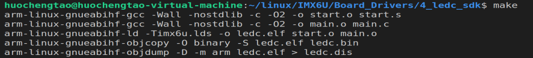
- 下载到SD卡中
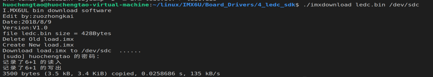
- 将SD卡插入开发板,led进行闪烁
三、IO函数
- 定义的GPIO1_IO03,与后面的函数对应属性
#define IOMUXC_GPIO1_IO03_GPIO1_IO03     		0x020E0068U, 0x5U, 0x00000000U, 0x0U, 0x020E02F4U

/*
	uint32_t muxRegister,								0x020E0068U
	uint32_t muxMode,									0x5U
	uint32_t inputRegister,								0x00000000U
	uint32_t inputDaisy,								0x0U
	uint32_t configRegister,							0x020E02F4U
	uint32_t inputOnfield或uint32_t configValue		   输入的值自己写
*/
- 引脚复用函数
/*!
 * @brief Sets the IOMUXC pin mux mode.
 * @note The first five parameters can be filled with the pin function ID macros.
 *
 * This is an example to set the ENET1_RX_DATA0 Pad as FLEXCAN1_TX:
 * @code
 * IOMUXC_SetPinMux(IOMUXC_ENET1_RX_DATA0_FLEXCAN1_TX, 0);
 * @endcode
 *
 * This is an example to set the GPIO1_IO02 Pad as I2C1_SCL:
 * @code
 * IOMUXC_SetPinMux(IOMUXC_GPIO1_IO02_I2C1_SCL, 0);
 * @endcode
 *
 * @param muxRegister  The pin mux register.
 * @param muxMode      The pin mux mode.
 * @param inputRegister The select input register.
 * @param inputDaisy   The input daisy.
 * @param configRegister  The config register.
 * @param inputOnfield   Software input on field.
 */
static inline void IOMUXC_SetPinMux(uint32_t muxRegister,
                                    uint32_t muxMode,
                                    uint32_t inputRegister,
                                    uint32_t inputDaisy,
                                    uint32_t configRegister,
                                    uint32_t inputOnfield)
{
    *((volatile uint32_t *)muxRegister) =
        IOMUXC_SW_MUX_CTL_PAD_MUX_MODE(muxMode) | IOMUXC_SW_MUX_CTL_PAD_SION(inputOnfield);

    if (inputRegister)
    {
        *((volatile uint32_t *)inputRegister) = IOMUXC_SELECT_INPUT_DAISY(inputDaisy);
    }
}
- 电气设置函数
/*!
 * @brief Sets the IOMUXC pin configuration.
 * @note The previous five parameters can be filled with the pin function ID macros.
 *
 * This is an example to set pin configuration for IOMUXC_GPIO1_IO02_I2C1_SCL:
 * @code
 * IOMUXC_SetPinConfig(IOMUXC_GPIO1_IO02_I2C1_SCL, IOMUXC_SW_PAD_CTL_PAD_PUE_MASK | IOMUXC_SW_PAD_CTL_PAD_PUS(2U));
 * @endcode
 *
 * @param muxRegister  The pin mux register.
 * @param muxMode      The pin mux mode.
 * @param inputRegister The select input register.
 * @param inputDaisy   The input daisy.
 * @param configRegister  The config register.
 * @param configValue   The pin config value.
 */
static inline void IOMUXC_SetPinConfig(uint32_t muxRegister,
                                       uint32_t muxMode,
                                       uint32_t inputRegister,
                                       uint32_t inputDaisy,
                                       uint32_t configRegister,
                                       uint32_t configValue)
{
    if (configRegister)
    {
        *((volatile uint32_t *)configRegister) = configValue;
    }
}

技术共进,成长同行——讯飞AI开发者社区
更多推荐


 0
0 0
0- 0


 已为社区贡献5条内容

所有评论(0)